Tiny AVR emulates Dallas DS2450 1-Wire Quad A/D Converter
Vladimir I. Yershov
Chloride Rus, Moscow, Russia
Abstract
This article describes basic approach to building 1-wire slave devices by uC emulation on example of DS2450 1-Wire Quad A/D Converter. Besides lower cost, emulated device allows to get more precision that the prototype and more flexibility by adding various extra software options. Also, 12 bit ADC conversion was realized by oversampling technique.
*** During the development no one Tiny was suffered or burned out.
The idea to replace standard DS2450 [1] came during the development battery monitoring system, when it became obvious that declared precision of the DS2450 does not exceed 8 bits.
The Hardware
.
ATTiny45 chip finally was chosen for the emulation although PIC12F675/683 also were tested but failed due to the speed limitations.
Tiny45 was configured for operation from internal RC clock at 8 MHz with RESET pin configured as analog input. Pin configuration shown on Fig.1.
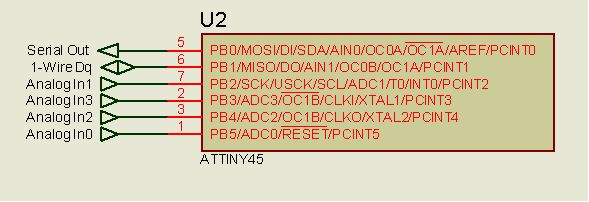
Fig. 1 Pinout of the design
A lab sample of the battery measuring board based on Tiny emulator shown below on Fig.2. As galvanic isolation is mandatory for such applications, there are two optocouplers on the sides of the board. So 1-wire communication is performed via optical link. But it’s a topic for another article.
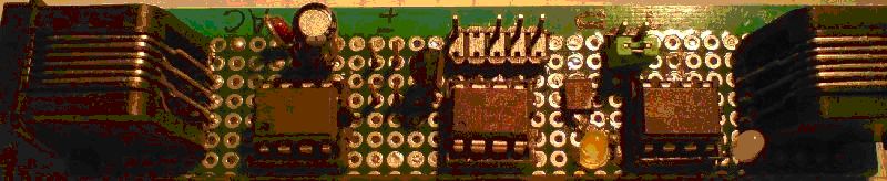
Fig.2 Sample board for battery monitoring system. Tiny is in the middle.
The Firmware
Present software version supports most basic operations of DS2450 except output pins control and alarms function. To achieve 12 bit resolution, a well known over sampling technique [2] was used.
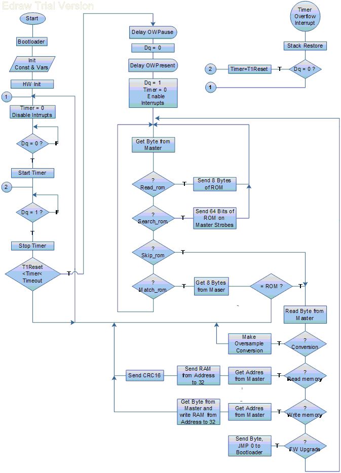
Fig.3 Simplified software flowchart
The design is also allows addressable firmware upgrade via 1-wire network with the Bootloader by Peter Dannegger [3].
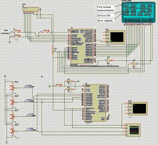
To demonstrate the operation of the device a compilation option for Mega32 (Tiny45 is not available for simulation) was added and Proteus simulation design was made.
Simplified software flowchart shown on Fig.3. The program flow divides into the several stages.
- Main Loop – polling of the state of the 1-wire pin Dq for Reset Pulse from Master. Once the low state of Dq has been distinguished Timer starts to counts and the program waits for High Dq. On the High Dq Timer stops and the comparison with the predefined Min and Max intervals made. If the pulse seems to be Reset the program performs output of the Presence Pulse and the program begin to wait a general command from the Master.
- General commands reception. General commands could be only: Read ROM, Search ROM, Skip ROM or Match ROM. If received byte corresponds to one of the General Commands the control passed to second command acquisition block which recognize device specific commands. Oversize flow returns to the Main Loop.
- Device specific commands reception. These commands for this emulator are: Start ADC Conversion, Read Memory (ADC results and settings), Write Memory (Device Setup) and Firmware Upgrade.
- ADC Conversion, according to the Oversampling Technique Idea executed 64 times with summing conversion results in word array for each ADC channel with subsequent division by 16 which results in 12 bit value. Resulting conversion time is similar with the prototype DS2450.
- CRC16 Calculation is necessary for 1-wire protocol requirements almost for any transaction. In this program CRC16 calculated for each sent/received byte on the fly immediately as the byte is available. It’s the task of CRC_Update subroutine.
- Interrupt Service Routine (ISR) on timer overflow used here to prevent program endless cycling in cases of transmition errors or if the master sleeps too long. It returns the control to the different points of the Main Loop depending of the state of Dq.
- Firmware Upgrade performed via 1-wire bus. This design was developed to work with the intermediate PIC uC which serves as a Master, accumulates, process data and send results to PC. At the beginning of FW Upgrade Master sent to Slave Bootload command byte. Slave responses with the same byte and jumps to Bootloader. Master come into transparent mode and translates the Bootloader traffic from PC to Slave and back.
- Tiny programming consists of two steps: 1. Flashing the Bootloader 2. Downloading Firmware via Bootloader.
Results
Testing of the design was performed in virtual and real environments. Real tests were done with 4 Tiny emulator modules, united in 1-wire net and connected to the 16 x 12V VRLA batteries of the 10 kVA UPS. Also modules based on DS2450 prototype were tested in the same conditions. Monitoring parameters were: battery voltage, charge-discharge current, measuring accuracy and transmition errors. Tiny modules shows better performance over DS2450 by all parameters except current consumption which was 1.5 times greater. There were no any power optimization in current version, so it’s optimistic to think it’ possible to improve in the future releases.
Proteus simulations were helpful for debug and presentation. Below is the screen short of such simulation.
Conclusion
There are no limits for perfection of course, but some obvious improvement must be done, e.i. possibility to reset and set ROM s/n on the fly, power consumption optimization and adding 5th analog measurement for internal temperature sensor of Tiny.
References
- DS2450 1-Wire Quad A/D Converter Datasheet http://datasheets.maxim-ic.com/en/ds/DS2450.pdf
- AVR121: Enhancing ADC resolution by oversampling http://www.atmel.com/dyn/resources/prod_documents/doc8003.pdf
- UART Bootloader ATtiny13 - ATmega644 http://www.mikrocontroller.net/topic/73196#1084470
1. Bascom AVR source code
2. Proteus sample simulation design
|